
Scratch
- Windows Compatible
- Mac Compatible
- Linux Compatible
- Not Chrome Compatible
- Not iOS Compatible
- Not Android Compatible
Product Details
Kindly note that S2P was designed for Scratch 2 offline. It will not work with Scratch 3.
Instead please consider our dedicated product for block programming, Blockly for PICAXE
Scratch (https://scratch.mit.edu/) is a popular free software package used in schools to introduce simple computer programming. Any PICAXE microcontroller system (e.g. the BOT115 Create system or Snap Circuits Micro) can be used to send real life signals (switch presses, light levels, position etc.) to the Scratch software so that the program can react to these changing conditions.
For a similar blocks programming language dedicated to the PICAXE system please also see Blockly for PICAXE.
What is S2P?
S2P is a free helper app for Scratch that expands the capabilities of Scratch by enabling you to simulate and program PICAXE microcontroller projects from within Scratch 2. It will work with most PICAXE project boards as well as the Snap Circuits Micro / XP microcontroller module (which is fitted with a PICAXE-08M2 microcontroller).
The S2P helper app is available for Windows, Mac and Linux.
S2P will also work with Snap! instead of Scratch. The Snap! templates can be downloaded here.
We also produce another free app, S2Bot, for Picoboard, Sphero and LEGO Boost, WeDo 2.0, WeDo, NXT and EV3.
Getting Started
- Video Tutorial 1 - Setting Up
- Video Tutorial 2 - Flash an LED
- Video Tutorial 3 - Using a digital sensor (switch)
- Video Tutorial 4 - Using an analogue sensor (LDR)
- Video Tutorial 5 - Remote Run Mode
- Video Tutorial 6 - Playing a tune on a real-life glockenspiel (using kit MOD028)
How does it work?
S2P interacts with Scratch in two separate, different ways –
Connected Mode:
In connected mode the Scratch project you have developed ‘talks’ to the S2P helper app on the computer, enabling Scratch to now also control real life outputs and respond to real-life inputs as the Scratch project runs. This is useful for developing and testing Scratch projects. In connected mode the PICAXE chip on the project board simply runs a small ‘communicator’ program that enables it to communicate with the S2P helper app via the AXE027 USB cable.
This mode can also be used with Snap! (instead of Scratch) if you prefer. The Snap! templates can be downloaded here.
Remote Run Mode:
In remote run mode the Scratch project is saved and then converted into microcontroller code which can then be downloaded into the PICAXE microcontroller. Therefore the computer can be completely disconnected and the code now runs entirely on the microcontroller. This is normally used for building real-life projects e.g. robots, that you want to run autonomously (by themselves).
How do I control inputs and outputs?
The S2P helper app ‘adds’ extra new blocks into the Scratch software. These new blocks automatically appear when you simply open the template Scratch (.sb2) file. These extra blocks enable you to control outputs (e.g. through the motor block) or detect changes in real-life inputs via new ‘reporter blocks’.
Are there any limitations to the blocks I can use in Scratch projects?
If you only use ‘connected’ mode there are no limitations, as the program still runs on the computer. So you can use all of Scratch’s blocks and interact with real life sensors e.g. move a sprite on screen or play a sound when an input switch changes in the real world.
However in ‘remote run’ mode some Scratch blocks no longer have any meaning, e.g. you cannot move a screen sprite, change costume or respond to a keyboard (simply because the PICAXE microcontroller does not have a screen or keyboard connected!) So these types of block should not be used in a remote run program. Within Scratch each script generally starts with a hat block, and then all scripts run at the same time in parallel. The PICAXE-14M2, 18M2, 20M2 microcontrollers each support up to 8 parallel tasks, so the 'remote-run' project should have no more than 8 hat blocks. However this is not generally an issue, as it is quite possible to code useful projects that only actually use one hat block.
Known Scratch Issues:
The build number of Scratch is shown at the top left, under the blue ‘full screen’ button. Please ensure you are using v426 or later.
- The Windows offline version of Scratch and/or Adobe AIR has a memory leak and often hangs after long periods of inactivity (e.g. if Scratch is minimised whilst you work on something else). If this occurs there is no option but to close and restart Scratch, so make sure you save your project often!
FAQ:
Is S2P free to use, even on school networks?
Yes, anyone can use them. You don’t need to ask for permission to install on school networks.
Can I use S2P with both the online and offline versions of Scratch 2.0?
Yes, you can use Scratch online or offline versions on Windows (XP+), Mac (10.6+) and Linux (we test with Ubuntu 32-bit). The helper apps are not browser plugins, they are separate stand-alone applications. This means they should work with the online version of Scratch in almost any browser.
Can I use S2P with Scratch 1.4 or Scratch 3.0
No, S2P uses the version 2 ‘http extension’ protocol which is not present in Scratch 1.4 or 3.0. It does however work with Snap!
Can I use on iPad or Android tablets
No, we currently only support Windows, Mac OS X, Linux for S2P.
However as an alternate Blockly for PICAXE can be used in any browser (and on Chromebooks).
How do I add the extra ‘microcontroller’ blocks into my Scratch project?
Simply open the default ‘template’ .sb2 Scratch files provided. The new blocks with then be instantly shown on the ‘Other Blocks’ tab. These template files also automatically scan for, and connect to, the helper app (look for the ‘yellow/green’ dot by the extension name on the ‘Other Blocks’ tab).
In the Offline version select File > Open
In the Online version select File > Upload from my computer
Downloads
| Scratch 2.0 | Main Scratch website |
| S2P Helper App (Windows XP, Vista, 7, 8) v0.13 | S2P for Windows |
| S2P Helper App (Linux) v0.13 | S2P for Linux |
| S2P Helper App (Intel Mac OS X 6+) v0.13 | S2P for Mac |
| Blockly for PICAXE | Blockly for PICAXE |
Revision History
0.13
(All) Amended to support Scratch v446 and later
(All) Allow GET header from non-Flash environment to support javascript based systems such as Snap!

0.12
(All) Amended to support new Scratch file encoding system used within Scratch v445 and later

0.11
(All) Optimised motor command processing
(All) Fixed issue when using procedures

0.10
(All) Fixed issue with ultra command pin allocation and default frequency on certain parts

0.09
(All) Infrared is now a separate command, result is placed into new IR variable
(All) Added infrared tv style (+1) command
(All) 40X2 pin configuration fixes
(All) Added sub procedure support (NB Scratch does not require a 'return', it is automatically implied)
(All) Added LCD command
(All) Added toggle command
(All) Added BASIC command
(All) 'Green flag' now resets all pins to default state before running

0.08
(All) Fixed issue where main window would not display correctly at startup
(All) Improved infrared sensor conversion for remote run mode

0.07
(All) Added language localisation from .PO files

0.06
(All) Corrected issue with PICAXE BASIC conversion of wait time less than 1 second
(All) Added warning message when too many parallel tasks (hat blocks) are used

0.05
(All) Added broadcast support
(Mac) Fixed issue creating New Project template

0.04
(All) Added New Project button to easily open template files in Scratch

0.03
(All) Added support for 4 motors (motors A-D on B.0-B.7)

0.02
(All) Added Nunchuck support
(All) Added NXT Color Sensor 2 and NXT Temperature sensor support
(Win) COM Ports now display FriendlyName for easier identification
(Win) Added COM Port List Refresh

0.01
(All) First beta release of S2P helper app for Scratch


Linux Users please note:

On 64-Bit Ubuntu you will need to add 32-bit compatibility (if not already done so):

sudo dpkg --add-architecture i386
sudo apt-get update
sudo apt-get install ia32-libs-multiarch

Also make sure your user name is a member of dialout:

sudo adduser your_user_name dialout
sudo reboot
Related Products
-
BOT115 PICAXE Create Starter Pack
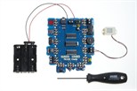
A modular electronics system that can be used with Scratch.
Details PDF ↓ -
AXE027 PICAXE USB Download Cable
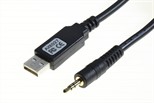
USB download cable for all PICAXE project boards
Details PDF ↓
Share