Uploaded
Submitted by: nickcinquino Project Website: N/A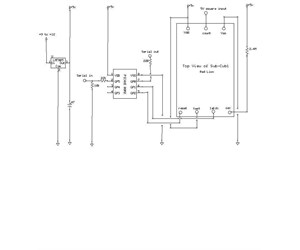
Uploaded
Submitted by: nickcinquino Project Website: N/A
Picaxe 08M2-controlled Frequency Counter - Nick Cinquino 4/11/13
This frequency counter project is a very handy item to have around when testing DIY circuits, to determine the frequency of a 5V squarewave, as are often found in digital circuits.
The counter is unique in that it is very inexpensive (about $10), and can be assembled by a beginner, on a breadboard, and operating within 2 hours! The program code is simple, and the parts count is insanely low, at under 10 components total!
OPERATION:
A Picaxe 08M2 is in control of a small LCD counter module. The code for the Picaxe is also very simple, only 11 lines long. The Picaxe takes care of 3 crucial functions. It creates the 1-second (1000 msec) sampling time, such that the digital reading is expressed in Hertz (counts per second), and it triggers both the latch (to "freeze" the reading), and the reset (to reset the previous count to zero). Here is the code for the 08M2:
main:
output 1, 2
high 1, 2
low 1
pause 10
high 1
low 2
pause 10
high 2
pause 980
goto main
Note that the total pause time equals 1000 milliseconds. Note also that this simple program is generating a 10msec low on pin 1 (to latch), followed immediately by a 10msec low on pin 2 (to reset)…and that's all that's needed to control a Red Lion Sub-Cub 1 component counter in frequency reading mode!
The Red Lion Sub-Cub 1 is a "complete 6-digit component counter". They are intended for vending machines, flow meters, test equipment, etc. Note that they are leadless; they are meant for solderless elastomeric interconnects, but that will not stop us from soldering short wire leads to the board, to make it pluggable into a breadboard. Simply hold a short 2cm piece of thin bare solid-core wire with a hemostat or tweezer to the board contact, and solder it down.
There are only 7 connectors that need to be added…+5 volts, ground, count (your signal under test), latch, reset, test (to +5), and osc (2.4 Megohms to +5). The Sub-Cub's spec sheet shows a schematic for frequency indication, and the Picaxe is single-handedly taking the place of 2 multivibrators and a bunch of critical resistors/capacitors plus an accurate 1Hz clock or timer. The spec sheet for new units can be found online at:
https://www.redlion.net/Products/Groups/DigitalInputs/SCUB1/2/Docs/09008.pdf
The specifications of your DIY frequency counter can be fairly impressive…if you can acquire an older, pre-2009 Sub-Cub1, the frequency display can be as high as 250KHz, so your counter instrument has a measuring range of 1Hz to 250KHz! The Sub-Cubs made after 2009 have a maximum count frequency of 10KHz, so that means your completed instrument is capable of 1Hz to 10KHz, still useful for the tiny handful of parts used. Accuracy seems excellent also; I estimate it to be within 1% or better, after testing several frequencies from a 555 timer and comparing the digital reading to the frequency determined on an oscilloscope.
The readings are very stable, which is a testament to the timing accuracy of the Picaxe. The Sub-Cubs also feature leading-zero blanking, meaning it will display "2500" for 2500Hz, instead of "002500"…a nice bonus.
The display is small; each digit is only 5mm high, but on the positive side, it means you can easily build a "pocket frequency counter", and carry it anywhere. The Sub-Cub1 is available from several sources. Best price would seem to be ebay at about $4 each in quantity of 5, or about $10 for one, as of this writing. Ebay search "sub cub counter".
CIRCUIT DETAILS:
An LM7805 voltage regulator takes the 9VDC or 12VDC supply and regulates it down to the required 5VDC. The 5VDC powers both the Picaxe 08M2 and the Sub-Cub. Simply wire it all up per the schematic, download the code to the Picaxe, and start accurately measuring frequencies! Just make sure that your input is a 5V squarewave.
For my initial tests, I added a 555 timer running at a bit over 20KHz and ran the output from pin 3 of the 555 into the count pin of the Sub-Cub, and saw a reading of 20410. Perfect!
An option to make the unit more versatile would be to insert a comparator, such as a 339 or 393, also powered by the same 5V supply, before the input to the Sub-Cub. That way, you could trigger on far lower voltage waves, and even start measuring non-square waves such as sine or sawtooth. The comparator would also serve to protect the input of the Sub-Cub from inadvertent input signals over 5 volts.
If you need to measure higher frequencies, adding a decade divider between the comparator and the Sub-Cub may help; you just have to multiply the displayed value times 10. I originally cooked up this circuit to assist in fooling around with infrared remote control circuits.
I built a Picaxe 14M2-controlled robot, and in one software setup, it is controlled by a TV remote. I decided that I wanted greater range, which meant that I got into building a higher power IR "repeater". To do that, I needed to re-add the modulation frequency of 38KHz back into the data stream…and to nail that precisely, I needed a frequency counter! This solution worked great; I was able to precisely tune the modulation frequency to exactly 38.0KHz using this frequency counter, and design an ideal range of adjustability of that frequency of 33 to 43KHz.

Share