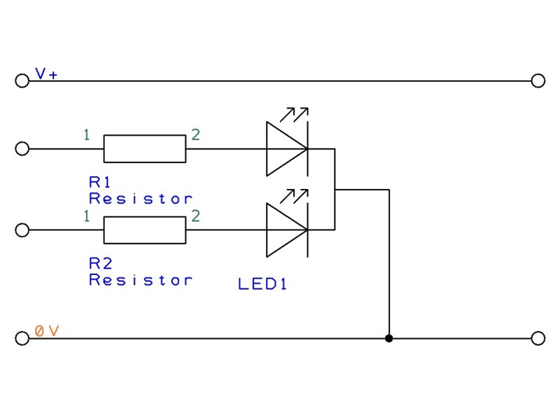
Tri-colour LEDs contain two LEDs connected in parallel often with a common cathode connection which normally connects to 0V. This will normally be the centre leg of the LED.
The two LEDs are often green and red. By turning one or both LED's on the light output can be red, green or orange.
To obtain a full range of colours an RGB LED can be used.
This program will cause a tri-colour LED to flash one colour and then the other. The LED anodes should be connected with inline resistors to output pin B.1 and output pin B.2 with the common cathode to 0V.
Code Example:
main:	high B.1	; Select one colour
	pause 250	; Keep the LED on for a short while
        low B.1		; Turn the LED off
	pause 500	; Keep the LED off for a while

	high B.2	; Select the other colour
	pause 250	; Keep the LED on for a short while
        low B.2		; Turn the LED off
	pause 500	; Keep the LED off for a while

	high B.1, B.2	; Select both colours together
	pause 250	; Keep the LED on for a short while
        low B.1, B.2	; Turn the LED off
	pause 500	; Keep the LED off for a while

	goto main	; Repeat
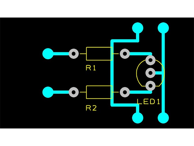
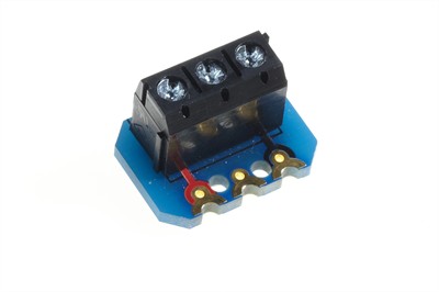
A tri-colour LED may be connected to two generic terminal block create modules.
The outer two legs of the LED should go to the centre connectors of each terminal block (each through a 330R series resistor). The centre LED leg should connect to one of the 0V connections of the terminal blocks.

Share